
Medical Electrical Devices: Choosing an Operating Altitude Rating
Choose a defensible operating altitude for medical electrical equipment, with clearance calculations, thermal evidence, and separate EMS and aircraft assessments.

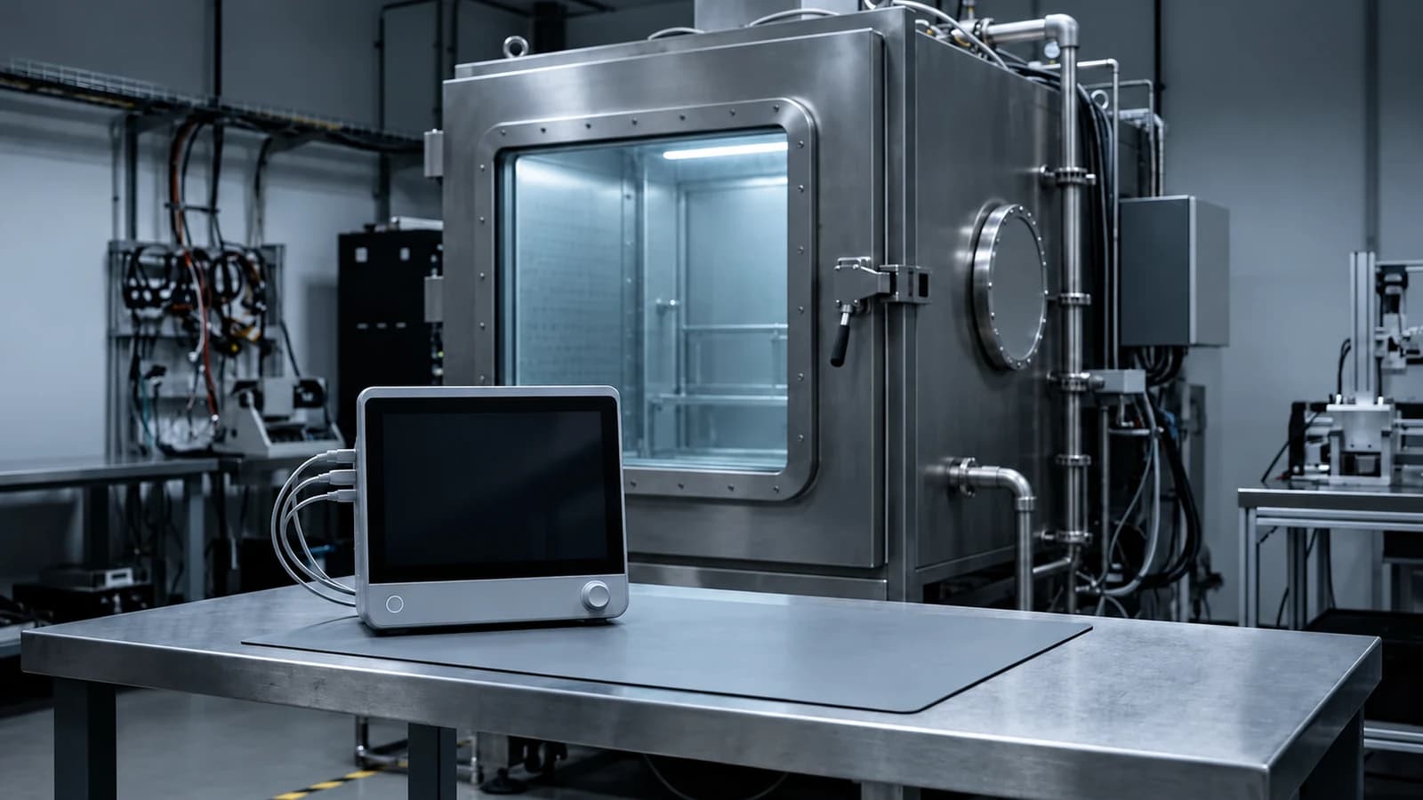
For a medical electrical device, choose the operating altitude from its intended environment before commissioning an altitude test. A report covering operation to 2,000 m does not establish a higher rating. For a higher claim, review air clearances, the creepage floor, cooling and device performance in the actual configuration. An ambulance or aircraft claim also needs an assessment of the relevant environment; surviving a low-pressure chamber run alone does not establish all of that evidence.
Consider an illustrative manufacturer whose monitor has a 2,000 m rating. A customer requests use at a facility above that elevation, and a distributor asks for an air-ambulance version. These are two decisions: extending the operating envelope and adding an EMS use environment. Start by obtaining the facility elevation and the aircraft pressure profile. Then identify the design changes and verification needed for each configuration. Neither request is answered by changing the sales brochure or copying a power supply’s altitude rating.
What the 2,000 m baseline actually establishes
IEC 60601-1 covers basic safety and essential performance of medical electrical equipment. The IEC catalogue identifies the consolidated Edition 3.2 as IEC 60601-1:2005+AMD1:2012+AMD2:2020 CSV. Collateral and device-specific particular standards can supplement or modify the general requirements, so selecting the general standard does not finish the applicability assessment. IEC edition and scope
The publicly hosted dental-unit CB report reproduces clause 8.9.1.5: where the manufacturer specifies no altitude, the form records an expectation of operation at 2,000 m or below. It also addresses manufacturer-specified altitudes and pressure-equivalent altitude in pressurized environments. This is evidence of the standard’s assessment mechanism, rather than a universal legal altitude limit or a guarantee of product performance. CB report, printed page 45
Record the proposed maximum operating altitude or pressure range as a design input. Identify the intended locations, operating modes, accessories and power sources. Reconcile the resulting supported claim with the instructions and other product information. The cited report does not establish a universal requirement to print an altitude value on every equipment nameplate; determine the applicable marking and accompanying-document requirements from the standards and rules used for that device.
Keep operation separate from storage and transport. A non-operating pressure limit describes a different exposure from providing the device’s intended function under reduced pressure. A packaging study can address a shipping risk without demonstrating energized electrical safety or performance. Conversely, an operating-altitude assessment does not automatically establish package integrity during distribution. Define the state of the equipment and the acceptance criteria before choosing either protocol.
Apply altitude correction to the right insulation assessment
Clearance is the shortest distance through air between conductive parts; creepage follows an insulating surface. The CB form records altitude correction of air clearances, with creepage left unmultiplied but at least as large as the resulting clearance. Texas Instruments’ SLUP419 explains how working voltage, transient conditions, pollution degree, material group and the applicable equipment standard affect spacing decisions. Its worked example concerns telecommunications equipment, so its base dimensions must not be imported as medical-device requirements. Insulation-coordination explanation
A real component report makes the distinction concrete. Advanced Energy’s hosted report E116994-D6015-CB-1 records a maximum operating altitude of 4,000 m, application of the Table 8 factor to MOOP clearances, and a 1.29 correction factor in its insulation assessment. The same report leaves integration matters for the end product. A certified supply is therefore useful evidence for the system assessment; its rating is not, by itself, a rating for the complete monitor. Power-supply CB report, printed pages 14 and 17
Use the following as calculation examples only. Assume the applicable assessment has already established a 2.00 mm baseline air clearance for a particular barrier. That starting value is hypothetical: it is not a requirement for any stated working voltage, MOOP or MOPP category. The 4,000 m factor is documented in the component report; the 5,000 m factor is documented in TI’s example.
| Assessment point | Factor evidenced here | Illustrative calculation |
|---|---|---|
| 2,000 m baseline | 1.00 reference | 2.00 mm before altitude correction |
| 4,000 m | 1.29 | 2.00 × 1.29 = 2.58 mm |
| 5,000 m | 1.48 | 2.00 × 1.48 = 2.96 mm |
After calculating a corrected clearance, compare it with the separate creepage requirement and the measured geometry. For an illustrative barrier with an independently established 2.50 mm creepage requirement, a 2.58 mm corrected clearance would raise the creepage floor to at least 2.58 mm. Record both checks. Do not round a required minimum downward, and distinguish the calculated minimum from the available production spacing and measurement uncertainty.
For another declared altitude, obtain the applicable factor and any permitted calculation method from the licensed standard and agree the assessment with the laboratory. This guide does not establish an interpolation method. Do not infer a factor simply from a rounded cabin altitude. The design record should identify the actual barrier, base spacing, altitude basis, factor, resulting minimum and measured spacing, rather than only a statement that altitude was considered.
Evaluate cooling independently of electrical spacing
Reduced air density can impair heat removal in both naturally cooled and fan-cooled equipment. Advanced Energy’s high-altitude application note presents different temperature-rise multipliers for different cooling arrangements and emphasizes meeting specification at the rated altitude. These are supplier design data, not universal medical-device derating percentages. A larger electrical clearance does not establish adequate cooling, and a supplier’s thermal recommendation does not establish the finished equipment’s performance. High-altitude power-supply application note
For the proposed rating, define a thermal evidence plan around the complete product: enclosure, installation orientation, ventilation, accessories, power supply, electrical load and ambient-temperature claim. Identify the conditions likely to produce the highest relevant temperatures and the performance measurements to observe. State the technical basis for selecting representative configurations. If a restriction on output or ambient temperature is needed, make it part of the supported operating envelope.
A chamber study may provide useful direct evidence. An engineering model may also inform test selection. Its adequacy depends on the applicable assessment; sea-level extrapolation cannot be assumed to replace required testing. Agree the proposed evidence with the evaluator before execution. Record model assumptions and validation, any remaining uncertainties, and which device conditions were actually measured.
Match the configuration to the evidence question
The following matrix is a planning aid. A single product may occupy several rows, particularly an EMS device installed in an aircraft. Determine the applicable editions, device-specific standards and market requirements before treating any row as a test specification.
| Intended configuration | Decision to resolve | Evidence to plan |
|---|---|---|
| Facility above the supported altitude | What maximum operating altitude covers the actual installation? | Documented altitude input; applicable insulation assessment; thermal and performance evidence for the finished configuration. |
| Ground ambulance or other EMS use | Does the intended use fall within the EMS collateral standard? | IEC 60601-1-12 applicability assessment and a protocol covering the relevant environmental and operating conditions. |
| Air ambulance | What pressure profile and EMS conditions reach the equipment? | EMS assessment plus aircraft-specific installation and exposure information; evaluate combined requirements rather than using a hospital report alone. |
| Equipment installed in an aircraft | What environmental qualification is accepted for this installation? | Agreed airworthiness compliance basis and applicable DO-160 categories or another accepted means; separate medical performance evidence. |
| Patient-carried device in a passenger cabin | Is the device rating suitable for cabin exposure, and which carriage/use rules apply to this device type? | Pressure-based operating assessment and device-specific acceptance review. Apply the FAA POC criteria only to portable oxygen concentrators. |
IEC 60601-1-12 adds requirements for medical electrical equipment intended for EMS environments, including care at an emergency scene and use during transport. FDA’s recognition entry also includes monitoring, treatment or diagnosis during transport between professional healthcare facilities. Those scope descriptions support an EMS assessment; they do not supply a complete pressure, temperature, exposure-duration or mounting specification. IEC EMS scope and FDA EMS recognition
Before writing an ambulance protocol, obtain the operating and non-operating conditions, exposure durations, recovery conditions and any device-specific modifications from the applicable texts. Do not use a laboratory summary’s pressure window as a continuous operating guarantee for every device. For air ambulances, establish whether the equipment is exposed to a pressurized cabin, an unpressurized compartment or changing pressure during operation. The aircraft’s flight altitude and the pressure at the equipment are different inputs.
Use cabin-pressure limits with their conditions
14 CFR 25.841 generally sets a normal occupied-cabin pressure-altitude limit of 8,000 ft, approximately 2,438 m. For certification above 25,000 ft, it generally limits occupant exposure after a probable pressurization-system failure to 15,000 ft, approximately 4,572 m. Paragraph (c) provides exceptions for operation into or out of high-elevation airports. The regulation also addresses other decompression failure conditions. These are aircraft requirements, not a universal medical-device test envelope or a statement of every flight’s actual cabin pressure. 14 CFR 25.841, Cornell reproduction
Even the general 8,000 ft example exceeds 2,000 m. That makes a cabin-use claim an altitude assessment rather than an automatic extension of a hospital rating. The CB form’s pressurized-environment approach uses the altitude corresponding to actual air pressure. Obtain the intended pressure profile and relevant failure exposure from the aircraft or installation requirements; do not assume that either normal cabin pressure or the aircraft ceiling alone describes the complete use case.
FAA AC 21-16G identifies DO-160 versions D through G as acceptable environmental qualification methods for certain airworthiness requirements and encourages version G for new articles. It explicitly says it is not mandatory and is not the only compliance means. It applies to manufacturers and installers using DO-160 for airborne-equipment qualification. Therefore, agree the applicable categories and procedures for the installation rather than prescribing every Section 4 altitude, decompression and overpressure test to all medical equipment carried aboard aircraft. FAA AC 21-16G
Portable oxygen concentrators have a specific FAA acceptance framework. The FAA page lists lawful US marketing, RF non-interference, no compressed-gas generation and hazardous-material restrictions. Qualifying POCs generally require manufacturer conformity labeling; previously listed models have a labeling exception. The page also publishes positive DO-160 Section 21 Category M results for listed models. These criteria are not a general acceptance route for infusion pumps, monitors or all patient-carried electronics, and RF evidence does not establish performance at reduced pressure. FAA portable oxygen concentrator criteria
Separate standards status from the product claim
United States: FDA Recognition 19-46 identifies ANSI/AAMI ES60601-1, including Amendment 2:2021, as a recognized standard. Recognition supports a voluntary consensus-standard route; it does not make every IEC clause a freestanding statutory requirement. Record the exact recognized edition and assess the applicable US adoption and device requirements when preparing conformity evidence. FDA recognition record
European Union: use the Commission’s MDR harmonised-standards page to check the applicable EN reference, amendments and Official Journal publication. Presumption of conformity is tied to the relevant published reference and covered requirements; the Commission warns that its summary itself has no legal effect. Do not assume that publication of the IEC consolidated edition establishes an identical European legal status or covers every product requirement. Commission MDR standards references
China: GB 9706.1-2020 is a mandatory national medical electrical equipment standard with an implementation date of May 1, 2023. Cisema’s overview supplies background on the transition, but does not establish national altitude deviations or special provincial rules. Check the applicable GB text and product-specific requirements before transferring an IEC assessment to a China claim. This guide does not establish a special altitude-marking rule for particular Chinese provinces. GB 9706.1 transition background
Build a reviewable altitude evidence package
The following is a recommended working package for design and RA/QA teams, rather than a mandatory document format. Its purpose is to make each proposed claim traceable to the configuration and evidence that support it. Start the package before asking a laboratory for a quotation, so the quotation can address an identified gap.
| Record | What to capture | Question it should answer |
|---|---|---|
| Operating envelope | Intended environments; maximum altitude or pressure range; temperature and operating modes; separate storage and transport conditions. | What exactly is the proposed claim? |
| Configuration definition | Model and revision; enclosure; supply; accessories; mounting; power sources; representative test sample. | Which released equipment does the evidence cover? |
| Insulation assessment | Applicable standard and barrier classification; base requirement; altitude correction; creepage floor; measured distances and margins. | Does the layout support the claimed altitude? |
| Thermal and performance plan | Loads, ambient conditions, orientation and cooling; acceptance criteria; test or analysis rationale and limitations. | Will the finished product meet the claimed operating envelope? |
| Environment applicability | EMS scope; aircraft installation basis where relevant; device-specific carriage/use criteria. | What additional evidence follows from the intended environment? |
| Claim reconciliation | Supported limits in instructions and product specifications; unresolved restrictions and review ownership. | Is the offered claim consistent with the evidence? |
For each laboratory activity, specify the question, sample configuration, exposure profile, operating state, observations and acceptance criteria. Agree which records will be delivered, including relevant pressure and temperature records, deviations and the final assessment. If a quote proposes a generic low-pressure run, ask which claim it addresses and which parts of the electrical, thermal or performance assessment remain outside its scope. A test name alone is not an evidence strategy.
For an existing product family, compare the altitude-sensitive differences before reusing evidence: insulation geometry, supply, enclosure, cooling and operating load. Explain why the tested configuration represents the proposed variant, or identify the additional work needed. Our guide to test-report coverage across device models addresses that separate coverage decision. Evidence for one component or model should retain its original conditions and limitations when incorporated into the altitude package.
Use the package to reach a specific disposition: support the proposed operating claim, support a narrower envelope, or identify verification still needed. For example, insulation evidence may support the proposed elevation while the thermal evaluation supports only a lower ambient temperature. Record that restriction explicitly instead of calling the device universally suitable for high altitude. For an EMS variant, complete the environment assessment before offering an ambulance-use claim.
Evidence limits and reassessment triggers
The public CB reports support the mechanisms described here, but they are product reports and do not replace the licensed standard or a device-specific evaluation. This article gives no universal base clearance dimensions, interpolation rule, continuous EMS environmental window or aircraft qualification category. Confirm those inputs before authorizing a protocol. Its calculation examples demonstrate arithmetic and the creepage comparison, not approval of an insulation design.
IEC has published a design specification for a fourth edition of IEC 60601-1. It is drafting material, not a replacement published standard. The Edition 3.2 catalogue’s 2028 stability date does not guarantee continued legal acceptance throughout the decade or determine any jurisdiction’s transition arrangements. IEC fourth-edition design specification
Reassess when the claimed environment changes, including a new facility elevation, an EMS use case or an aircraft installation.
Reassess after changes to the supply, spacing, enclosure, ventilation, load or accessories that could affect the altitude evidence.
Recheck the applicable IEC and national editions, FDA recognition records and Commission references when planning new conformity evidence.
Recheck aviation qualification and device-specific acceptance criteria when the installation basis, aircraft exposure or device type changes.