
EMC Test Configurations: Why the Cable and Accessory List Matters
How to record cables, accessories, and operating modes across EMC test plans, reports, and labeling, and assess configuration changes under FDA guidance.

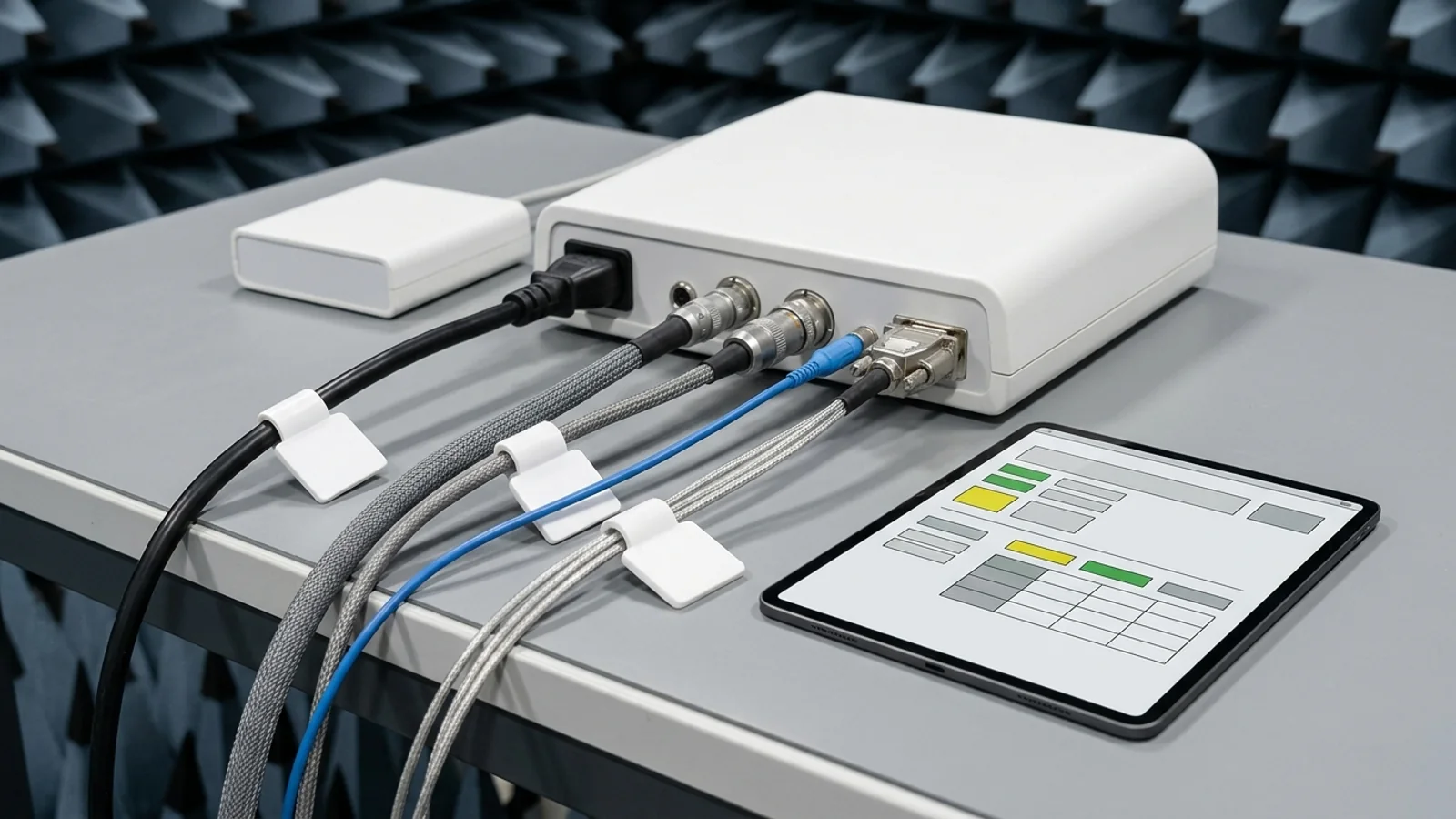
A passing electromagnetic compatibility (EMC) report supports the configuration assessed in testing. Reusing it after changing a cable, adding an accessory, or substituting a tablet requires an analysis of whether the previous evidence still supports the marketed system. A different configuration does not automatically mean a failed device, but a passing verdict alone does not establish coverage. The cable and accessory list should let a reviewer connect the device description, test plan, results, and labeling to the same system.
Consider this illustrative scenario: a console was tested with a 0.8-meter shielded USB cable, but the proposed shipping configuration uses a 2-meter unshielded cable and a third-party tablet. The existing report is not automatically evidence for that combination. First identify both changes, assess their potential EMC effects, and check whether the tested configuration represents the updated system. FDA recommends new testing if that analysis indicates the prior results might not support the updated model or version. These lengths are hypothetical identity examples, not test-applicability thresholds or measured results.
The principal source is FDA's final EMC guidance, issued June 6, 2022. Its Federal Register availability notice identifies docket FDA-2015-D-3787. The guidance applies to electrically powered medical devices and accessories, including in vitro diagnostics, and devices with electrical or electronic functions or sensors. Its recommendations use “should”; alternative approaches can satisfy applicable statutes and regulations. The workflow below organizes those recommendations into manufacturer records. It is an editorial template, not an FDA-prescribed form or a guarantee of clearance.
What FDA means by testing the device as a system
Section IV.E, Medical Device Configuration and Functions Tested, recommends testing the device with all medical device accessories, components, and subsystems connected and functioning as intended. Non-medical equipment should also be included when it is used in the system and could affect the medical device's ability to meet its immunity pass/fail criteria. FDA gives phones, tablets, and computers as examples. Whether the manufacturer supplies the tablet does not resolve that functional question: the relevant issue is how the equipment participates in the intended system.
Start with an inventory of the intended configuration, including external interfaces, relevant accessories, power arrangements, and software or firmware versions needed to identify the setup. Then reconcile that inventory with what the laboratory actually tested. An omitted accessory or subsystem should remain visible in the record. FDA recommends listing untested non-medical equipment, medical device accessories, and subsystems with a reason for exclusion and providing a scientific justification that the test configuration demonstrates EMC of the entire system. An empty row is not an exclusion rationale.
Subsystem testing also needs an explicit boundary. Section IV.E recommends simulating each subsystem excluded from the test, including potential third-party devices or connections. For a multifunction device, the test specifications should consider the EMC standards applicable to its subsystems, accessories, and functions. A practical record therefore identifies the real subsystem, what simulated it, the functions represented, and the justification connecting the subsystem results to the whole system. This guidance does not establish a universal simulator design or a single test setup for every product.
FDA recommends testing the final finished device. If another build was tested, the description should explain and scientifically justify how the results apply to the final device. Record the device name, model number, manufacturer, and production-readiness status. These identity details prevent a report about an engineering build from silently becoming a statement about a later commercial build. They also give the change reviewer a concrete baseline against which to compare later cable, accessory, and software substitutions.
Which cable and accessory identities to record
Section IV.A recommends an overview of functions and modes, with block diagrams, photographs, cables, relevant accessories, and interoperability information. Section IV.E connects that description to the tested configuration. To make those recommendations usable, the crosswalk below adds practical engineering identity fields: model or part number, revision, cable length, shielding description, connector type, connected port, and role in the system. FDA does not prescribe this exact field list. Select enough detail to distinguish items whose substitution could change the evidence boundary.
For power items, identify the supply and the cable together, rather than recording only “mains powered.” For signal cables, preserve the measured or specified length and relevant construction description. For patient-coupled accessories, identify the accessory and the simulator or loading arrangement used to represent the patient where appropriate. For third-party equipment, identify the model and relevant version or configuration. A photograph can help locate an item, but it should not be the only way to determine which revision, cable, or operating state was evaluated.
The IEC catalog for IEC 60601-1-2:2014+AMD1:2020 CSV identifies Edition 4.1, published September 1, 2020. Its abstract describes immunity tests and levels according to equipment or system ports and intended-use environments. That makes a port-by-port inventory useful. The catalog does not supply the complete clause text for cable-length applicability, test levels, or setup geometry. Determine those details from the applicable standard and justified test plan; do not turn a cable length in this article into an automatic exemption or retest rule.
Define how equivalent-looking items will be distinguished before testing. For example, two USB cables may share a connector type but differ in length or shielding. Two power adapters may supply the same nominal voltage while being different models. An editorial inventory can use an internal item identifier to link each physical item to the description, plan, and report. That identifier is a traceability aid; its existence does not prove EMC equivalence between alternate suppliers or accessory combinations.
Operating modes and monitoring belong in the same record
Hardware identity alone does not describe the assessed system. Section IV.E recommends modes and settings representative of intended use, including functions whose failure could create unacceptable risk or prevent intended operation. Section IV.D recommends immunity acceptance criteria that are quantitative, device-specific, and observable, documented in the test plan before testing. Link each selected mode to the functions monitored and the relevant criteria. A statement that the unit was powered on does not explain whether the clinical function or data connection was active.
Power modes: FDA recommends testing both battery and mains modes when the device operates in both. Section IV.A also recommends describing whether an internally powered device can be used while charging. Record how the selected test states represent that intended operation.
User-handled smart batteries: the separate ESD recommendation applies to batteries with embedded electronics that are intended to be handled by the user. FDA recommends removing those batteries and testing them separately for ESD immunity. Record the battery identity and assessment; this is not a blanket instruction to remove every internal battery.
Wireless operation: when wireless technology is used to achieve intended use, FDA recommends that it be on and communicating with subsystems or ancillary equipment during EMC testing. Record the participating equipment and operating state. The guidance does not prescribe a universal channel matrix in this section.
Patient simulation and monitoring: use patient simulators where specified by the referenced standards or appropriate to the device. Describe how performance was observed quantitatively against immunity criteria without significantly perturbing the test or the device. FDA does not require one particular camera, telemetry medium, or monitoring instrument.
Keep the distinction between a mode and a configuration clear. A single cable-and-accessory combination can have several operating modes; a single mode may be evaluated with more than one configuration. Use a configuration identifier and mode identifier together when connecting a result to its setup. If a function was excluded, explain why the remaining assessment represents intended use. This record structure is a practical way to implement the guidance, not permission to omit an unfavorable or clinically important operating condition.
The crosswalk: one configuration item, four records
Use the device description to establish the system inventory, the test plan to state what will be connected and exercised, the report to establish what was assessed and what happened, and labeling to communicate supported compatibility and conditions of use. The following crosswalk compiles Sections IV.A, IV.D, IV.E, IV.F, and IV.K of the FDA final guidance. Item-level fields and change questions are editorial implementation suggestions. The rows identify categories to consider, not a fixed list required for every device.
| Item and identity in device description | Test plan | Test report | Labeling compatibility | Exclusion record | Change-review question |
|---|---|---|---|---|---|
| Power supply and cords: model, revision, connected port, cord identity and length. | Identify mains, battery, and relevant charging states representing intended use. | Identify the actual supply and cords associated with each assessed configuration and result. | Describe supported power arrangements and any relevant installation conditions. | Explain an omitted supply or relevant arrangement and how the tested setup represents it. | Does a replacement supply, cord, or power mode remain supported by the prior assessment? |
| Signal cables: item identifier, length, shielding, connectors, endpoints, and function. | Connect the planned cable and specify the active function or data connection. | Reconcile actual cable identity and setup with the plan; disclose differences. | Keep permitted accessory and cable combinations within the assessed compatibility boundary. | Explain an excluded connection or accessory and the basis for system representation. | Could length, shielding, connector, or connection changes affect EMC or test applicability? |
| Patient-coupled accessory: model, revision, function, and associated lead. | Identify patient simulation or loading where specified or appropriate. | Identify the accessory and simulator used and the monitored performance. | Identify compatible accessories and relevant conditions of use. | Explain what an omitted accessory or simulator represents and why exclusion is justified. | Does a new lead or simulation arrangement change the basis for the results? |
| Battery with electronics: model, revision, and whether the user handles it. | Represent battery operation; separately assess ESD for user-handled smart batteries. | Record the battery identity, assessed state, and separate results where applicable. | Describe supported battery arrangements and relevant mitigations. | Explain omitted battery configurations and any limits of representation. | Could changed electronics or user handling affect prior EMC coverage? |
| Wireless subsystem: module or device identity, relevant version, and communicating partner. | Keep intended-use wireless connections on and communicating. | Identify active connections and how relevant functions were monitored. | Describe supported equipment and relevant wireless precautions. | Explain an omitted subsystem or connection and how it was represented. | Does a module, software, partner, or operating-state change affect EMC? |
| Third-party equipment and excluded subsystems: model, version, role, and interface. | Include equipment that could affect immunity criteria; identify subsystem simulation. | Identify what was present or simulated and connect it to the results. | Name or describe equipment with which compatibility has been determined. | List untested equipment or subsystems, reasons, and scientific justification for system EMC. | Does a substituted tablet, computer, or subsystem invalidate the representation? |
Use this crosswalk as a reconciliation tool. If the plan calls for cable A and the report identifies cable B, determine which cable was actually tested before accepting the report. If the report does not identify the accessory revision, resolve that omission with the laboratory and the controlled test records. If labeling permits a wider combination than the assessment supports, narrow the statement or establish the missing evidence. These are documentation decisions tied to the test boundary; they do not presume that every discrepancy has the same technical consequence.
For the illustrative longer-cable-and-tablet scenario, create separate change entries for the cable and tablet, then assess their combined system use. Preserve the old configuration as the baseline rather than silently replacing its inventory. Record the new cable identity and construction, the tablet model and relevant software state, the interface, and which functions depend on that connection. The resulting analysis should explain whether the prior setup represented the new one. A shared configuration identifier makes that reasoning findable across the records without implying a predetermined passing outcome.
Connect the configuration to results and bench modifications
Section IV.F recommends the facility name and location, testing dates, results for each emissions test expressed against its limits, and results for each immunity test. For continuous phenomena, the summary should address degradations during and after testing; for transient phenomena, it should address degradations after testing. It should explain how observed degradations met the immunity criteria and identify additional mitigations. Connect these results to the relevant configuration and mode so that a reviewer can understand the scope of the verdict.
Keep allowances, deviations, and modifications distinct. Section IV.G describes allowances as variations or exemptions provided by the standard, usable only when their conditions are justified. Section IV.H describes deviations as intentional departures outside what the standard specifies or allows; these need a justification addressing safety and performance. Section IV.I addresses changes to the device made to pass testing. Recording all three as “not applicable” or “lab adjustment” loses the explanation of what the evidence actually represents.
FDA lists ferrite beads, filters, shielding materials, firmware or software changes, and even changes to metallic labeling material as examples of modifications that can alter EMC. Section IV.I recommends describing modifications, stating whether reported results occurred before or after them, stating that the changes will be incorporated into the final finished device before marketing, and assessing effects on other safety or performance aspects. If no testing followed a modification, the guidance recommends a risk analysis and scientific justification addressing the modified device.
As an illustrative production check, suppose a ferrite was added to obtain passing results. Identify its location and the assessed configuration, then reconcile that configuration with the released cable assembly and relevant production records. A report for the modified assembly does not automatically support an assembly shipped without the ferrite. Investigate the effect of that difference and establish whether the assessment remains applicable before relying on the report for the shipping configuration.
When reconciling an older report, separate its EMC evidence from the regulatory terminology used when it was written. The 2022 guidance includes design-control references from its publication date. Maintain production changes through the applicable quality-system process and keep the supported configuration identifiable in the released records. For a broader discussion of change documentation, see the site's medical device change-control guide.
When a configuration change calls for new testing
Section IV.E recommends three steps when applying prior results to another model or version: identify and summarize all changes, including changes in indications, intended use, and environments; analyze whether each could affect EMC; and assess whether the earlier standard has been superseded or replaced. FDA recommends new testing when any of those analyses indicates that the old results might not support the updated device. The same considerations apply when testing only a subset of models in a product family.
The decision table below applies that sequence to configuration changes. It deliberately identifies assessment questions rather than assigning an automatic test list. The scope of any additional testing depends on the device, applicable methods, risk assessment, and evidence gap. Preserve the analysis even when it supports reuse. A short assertion that a replacement is “equivalent” does not explain which properties, functions, or conditions were compared, or why the prior results remain representative.
| Proposed change | Compare with the tested configuration | Decision based on the analysis | Record to retain |
|---|---|---|---|
| Longer or differently shielded signal cable | Length, construction, connectors, endpoints, function, and applicable test specifications. | Perform new testing if the analysis indicates prior results might not support the changed configuration. | Old and new identities, EMC analysis, and evidence supporting reuse or new results. |
| Different tablet, computer, or external accessory | Model, relevant version, connection, intended function, and possible effect on immunity criteria. | Assess the updated system and any prior exclusion or simulation rationale. | System inventory, representation justification, and configuration-linked results. |
| Replacement supply or smart battery | Power modes, supply identity, battery electronics, charging use, and user handling. | Review whether the prior power-state and battery assessments remain applicable. | Power configuration, affected functions, and assessment or additional test record. |
| Firmware, wireless subsystem, or operating-mode change | Changed functions, communicating partners, settings, and monitoring criteria. | Reassess representation of intended use and whether prior EMC evidence remains sufficient. | Version comparison, mode matrix, and justification or new test results. |
| Changed standard or intended environment | Earlier edition and test scope, relevant revisions, and newly intended conditions. | Assess support for the proposed model or version; a standards update alone does not automatically require reassessment of an already cleared or approved device. | Standard comparison, environment analysis, and evidence-gap decision. |
That last distinction matters: Section IV.C explicitly says a cleared or approved device does not need reassessment or resubmission solely because an FDA-recognized EMC standard changes. This is different from deciding whether prior results support a changed model or version. The crosswalk also does not determine whether a product change needs a new 510(k) or another regulatory submission. For evidence covering several models, use the separate test-report model-variants guide alongside the configuration analysis.
Scope boundaries for IVDs, implants, and environmental emitters
Choose the assessment route before applying a configuration template. Section IV.C says most laboratory equipment and IVDs fall outside IEC 60601-1-2. At issuance in 2022, FDA partially recognized IEC 61326-1:2020 and IEC 61326-2-6:2020 and recommended their test methods, device-specific acceptance criteria, and IEC 60601-1-2 test levels or reasonably foreseeable maximum levels for the intended environment. That is a dated guidance statement, not a verification of every standard's current recognition. The identity workflow remains useful while the applicable tests differ.
Active implantable devices are also outside IEC 60601-1-2. The guidance references standards such as ISO 14117 for implantable cardiac devices and the ISO 14708 series, and recommends appropriate non-implantable standards for external subsystems such as programmers. Do not treat the implanted component and its external equipment as one undifferentiated test item. Record each subsystem's role and the evidence connecting their assessments to the intended system.
Section IV.J addresses emitters that may not be adequately covered by the referenced standards. For devices in harm-related risk categories, it recommends testing for foreseeable emitters using appropriate standards or justified equivalent methods. For RFID, its examples include AIM 7351731 and IEC 60601-1-2:2020 Clause 8.11. For devices without reported or potential harm, its recommendation emphasizes labeling; specific emitter claims still need supporting assessment. This does not justify treating every RFID, NFC, MRI, and wireless-power exposure as the same universal test.
FDA's Section IV.C also explains that a standard's recognition can include non-recognized clauses, acceptable deviations, and transition conditions. Check the current recognition information for the standard and edition used in a submission. The IEC catalog establishes publication identity and scope, not FDA recognition or EU harmonization. For the broader EMC standard overview, see IEC 60601-1-2 EMC testing. This article's decision remains the traceability of the assessed cables, accessories, and modes.
Check the evidence boundary before submission
Section IV.K recommends labeling that identifies accessories and other equipment with which compatibility has been determined, environments of use, compliance levels, relevant degradations, and mitigations or precautions. Match compatibility statements to the supporting configuration record and analysis. An untested item may be represented by justified evidence, but its coverage should be explicit. A generic statement that the device accepts “any compatible cable” or “any tablet” is broader than a record identifying a specific tested combination unless additional evidence establishes that broader boundary.
Identity: can you identify the device build, cables, supplies, accessories, and relevant versions assessed in each configuration?
Completeness: is relevant non-medical equipment included, or is its exclusion supported by a reason and scientific system justification?
Modes: do the recorded states represent intended use, including applicable power arrangements and active wireless connections?
Monitoring: were quantitative, observable immunity criteria established before testing, and is the monitoring method described?
Results: are facility details, dates, emissions limits, immunity results, and observed degradations tied to the assessed setup?
Modifications: do the results identify whether they preceded or followed changes, and does the final production configuration incorporate the supported changes?
Reuse: have changes and relevant standard revisions been analyzed without assuming either automatic equivalence or automatic retesting?
Labeling: does the supported compatibility statement describe the equipment and conditions of use actually established by the assessment?
Section IV allows recommended information to reside in reports, report summaries, or other submission sections when the EMC section points to its specific location. It mentions ASCA summary test reports as an example. The same traceability exercise can therefore check a summary against its underlying configuration evidence, without assuming an ASCA-specific field mandate from this guidance. The site's ASCA evidence-package guide and 510(k) submission-structure guide address those broader packaging decisions.
This template supplies no measured EMC results, universal cable threshold, equipment approval, or purchased-standard setup instructions. It supplies a way to make the actual assessment boundary inspectable. Resolve a mismatch by documenting what was assessed, explaining why it represents the proposed system, or obtaining the missing evidence. Keep that explanation attached to the configuration so that later changes can be reviewed against an identifiable baseline.